

Tutorials
Here you will find tutorials for the topic Game Development.
| Converting Ms3d-animations to DirectX | Date: 12.5.2010 | Author: Christoph P. | Difficulty: Medium |
| Introduction to DirectX Shader | Date: 15.5.2010 | Author: Christoph P. | Difficulty: Easy |
| Dual Paraboloid Shadow Mapping | Date: 23.5.2010 | Author: Christoph P. | Difficulty: Medium |
| Introduction to Milkshape 3D | Date: 17.6.2010 | Author: Christoph P. | Difficulty: Easy |
Introduction to Milkshape 3D
Preface
Milkshape 3D is a 3d modeling software, which is very suitable especially for beginners. This tutorial shows, how a simple wind turbine is modeled, textured and animated. It provides a comprehensive insight into Milkshape 3D. It is suitable for both novices and advanced users.
The following chapter is intended primarily for novices, it gives a brief overview of the features of Milkshape 3D. All who have already worked with Milkshape 3D, can skip this chapter.
Those who have not yet installed Milkshape 3D on their PC's, can download a 30-day trial version from here.
Overview of Milkshape 3D
Milkshape 3D offers the most important functions needed, to create and animate 3D models.
The smallest unit of a Milkshape 3D model, is the vertex. The vertices in turn, form the basis for the triangles, and the triangles
the basis for the whole models. If you map pictures on the triangles (Texture Mapping), you get a model that is also
nice to look at. If you then put the model to move (Animation), that describes altogether what MilkShape 3D enables us to do.
Now to the functions and tools: On the right side are four tabs.
In the first, called Model, the most important modeling tools are placed. With these tools, objects can be selected, moved, rotated, scaled and new primitives (simple objects) and joints can be added.
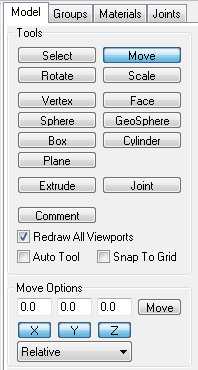
Model tab
In the Groups tab, the triangles (called faces in Milkshape 3D) are grouped for the assignment of materials. A material determines how the surface should appear, i.e. what colors and textures should be assigned to the surface. For grouping, the triangles are selected with Model->Select->Face and by Groups->Regroup the groups are formed.
In the Materials tab, the appropriate materials can then be created by clicking on New. With the 'none' - buttons, up to two textures can be determined and above the buttons, the colors can be selected. To assign the materials, the groups must be selected first, via Select in the Groups tab and with Materials->Assign they can then be associated to them.
The last tab Joints is used, to assign vertices to joints, which are previously added to the model. To do so, you choose the vertices with
Model->Select->Vertex and with Joints->Assign you are associate them with the currently selected joint. Joints->SelAssigned helps you
to verify the selection afterwards. By the way, the selection is independent of the selection in the Groups tab.
With the below located section Vertex Weights an animation technique called Skinning can be realized, however,
beginners can ignore it.
As well as the section Smoothing Groups on the Groups tab, which plays a role for advanced lighting.
At the bottom in Milkshape 3D is the animation bar, which can be activated by clicking on the Anim button. Joints and their associated vertices are animated on it by recording poses of the model to keyframes, at any time intervals. The keyframes are set with Animate->Set Keyframe. The pictures (frames) between the intervals are then calculated by the software.
And finally a few words about the menu. There are many useful tools and important functions, such as Edit->Duplicate Selection for copying selections, Vertex->Mirror for mirroring and Vertex->Weld To Nearest for welding vertices. The animation tools are in the menu and numerous import and export opportunities for various file formats.
Modeling of the wind turbine
First of all, we model the rotor. Aptly, in Tools->Extended Primitives->Mechanical->Propeller 3 there is a propeller that looks similar to a rotor, as we need it.
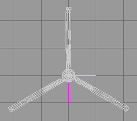
Propeller
Because we don't want the bent sections, at the end of the propeller blades, we remove them and move the remaining end plates to the new ends. This will require, that the triangles of such a section, must be selected with Model->Select->Face and deleted with the Delete key:
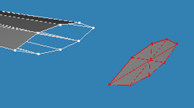
Propeller blade ends
- If you want to select multiple objects, you can drag a rectangle over the desired objects by mouse-left-click.
- If you want to remove objects from a selection, you can drag the rectangle over the desired objects, by mouse-right-click.
- If you want to add or remove additional objects to the selection, you should hold down the Shift key, while selecting.
- If you only want to select triangles, that are facing to the front, or vertices of such triangles, you can enable the checkbox Ignore Backfaces in the Vertex- or Face Select Options.
- Especially, when selecting triangles, you can use the checkbox - By Vertex, which allows you to select triangles by clicking on vertices.
If the objects are heavily nested in each other, selecting objects is often difficult. In this case all views of Milkshape 3D should be used for the selection. In the context menu (mouse-right-click), submenu Projection, are all views available in Milkshape 3D.
Now, after clicking on Model->Move, we drag the remaining plate, left from the propeller, with the mouse to the new end of the propeller plate. In order that no gaps are produced between the triangles, the seam along the vertices should be welded together. We select all vertices of the seam (the vertex in the middle of the plate should not be selected) and click on Vertex->Weld To Nearest in the menu. Who wants to check whether it worked, can view the number of vertices in the menu Tools->Show Model Statistics before and after welding. If the number is lower, it can be assumed that it was succesful. For this kind of welding, there is also an alternative, via Ctrl + N (Vertex->Snap Together) multiple vertices can be set to the same position. But for our case, that would mean we can edit only two vertices at once and thus would be more work to complete.
For assembling triangles or other exact work, it is recommended to zoom the view via mouse scrolling. Inaccuracies can cause e.g. gaps between the triangles, which look very unprofessionally, when the model is rendered. Hold down the Shift key to zoom faster.
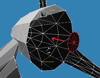
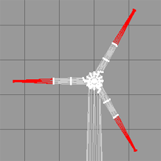
This process has to be repeated on all blades now, and as a reward we can then call the propeller rotor. To make the rotor still look more like a rotor, we sharpen its blades. On the following picture, the locations are marked red, which we have to scale separately from each other:
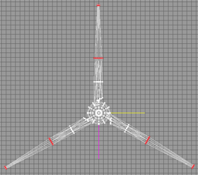
Scaling the rotor
After we have selected the appropriate vertices, we do the scaling via Model->Scale->Scale and the beside-lying textboxes.
For the outer vertices we use as value ca. 0.25 and for the inner ca. 0.75. These values we write each in each textboxes
and then we click on the Scale button beside it.
Next we create our own base plate for the rotor hub. To do this, we remove everything, except the small dodecagon at the bottom:
Base plate of the rotor hub - a
You should now have the basic knowledge for dealing with triangles, including removing them. Therefore, from now, I will confine statements,
regarding this, to a minimum.
The aforementioned dodecagon should now be scaled on the X- and Z-axis by Model->Scale and mouse (left-click and drag), so,
that it can be used as new base plate, to see in the following picture:
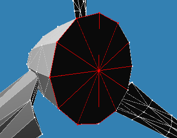
Base plate of the rotor hub - b
This plate must then be welded, like the end plates of the rotor blades before, via Vertex->Weld To Nearest; and the rotor is finished.
Now we need the enclosure, called nacelle in terminology. We select the triangles of the rotor hub and in the menu we click on Edit->Duplicate Selection at first and afterwards on Vertex->Mirror Top <--> Bottom. The result should then equal that on the following image:
Mirroring the nacelle
In the context menu, Draw Backfaces should be disabled by default, because you can easily overlook missing or wrong oriented triangles otherwise.
Then we push the two pieces together, but this time we don't weld it, because the rotor should rotate when animating later:
Assembling the nacelle with the rotor hub
To avoid that objects are transformed in undesirable directions, when you move or scale them via mouse, you should lock the axes, which are not used. In the Model tab there are X,Y,Z - buttons below the textboxes for all types of transformations. The desired axes can be locked or unlocked with them.
For the next structural measures, it is necessary to rotate the modeled until now, in its final intended position. To do this, select all and write 90.0 in the textbox above the Z-button in Model->Rotate. By clicking on Scale, everything will be rotated 90 degrees around the Z-axis.
Before we now finalize the nacelle, we create the tower, to match it with the nacelle. That is done quickly, because we only need a
suitable cylinder, that is a little wider below, than above.
We click on Model->Cylinder and change the options to 1 stack and 'Don't close'.
Then we drag up a cylinder, using the mouse in a frontal view. This cylinder and also the rotor with the nacelle, we adjust so, that the picture
corresponds to that of a wind turbine. We then scale the lower vertices by writing 2.0 to all textboxes in Model->Scale and clicking on Scale.
This should then look something like this:
Assembling the wind turbine
If you often switch between selection and transformations in the Model tab, it is recommended to use the function keys F1 to F8. This also works if you are just working on another tab.
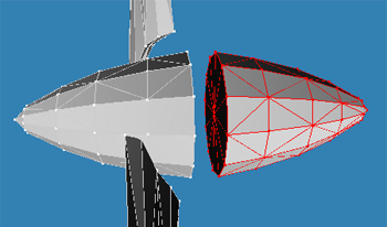
At last the nacelle will be finalized. See the picture:
Modeling of the nacelle
First the rear part of the nacelle should be somewhat stretched and also scaled on the X- and Z-axis, so that the second ring of vertices,
is the same size as the first. To get the rounding on the rear, the other rings must also be scaled on this axes.
With alternating scaling and moving, it should then look something like the picture above. If the work on the nacelle is complete, you can
merge it with the tower. Welding is not necessary here.
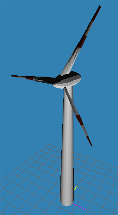
Place the now finished wireframe model (Mesh), with the center of the lower end of the Tower, on the coordinate origin, to provide
an easier positioning on later uses, e.g. before rendering with an engine. The following picture shows the result of this chapter, the finished mesh:
Result - Modeling
Texturing of the wind turbine
As described above, the triangles are now combined into groups and materials are assigned to them. The necessary textures can be created easily using a graphics program, because it is only a small white and a slightly larger, red-white-red texture. The red-white-red texture is used for the tops of the rotor blades and the pure white texture for the remaining model. We start with the creation of the materials:
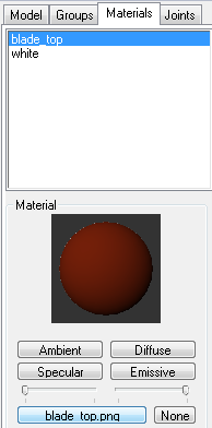
Materials tab
Clicking on Materials->New creates new materials and clicking on Materials->Rename changes the names of materials. We leave the colors by their default values, but the paths of the two textures must be specified with a click on the upper of each of the two Materials-> 'none' - buttons, so that MilkShape 3D can find them. Then we define the groups, those the appropriate materials are assigned to:
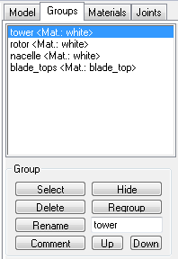
Groups tab
Actually two groups, for two materials, would be sufficient. But for better editing, I have divided the model into four groups:
tower, rotor, nacelle, blade_tops.
Grouping is not difficult: the desired triangles are selected via Model->Select->Face
(vertices do not work) and clicking on Groups->Regroup afterwards, set the groups. With a click on Groups->Select you can check whether it worked.
That's all about.
Now divide the model into the groups mentioned. The group of the rotor blade tops looks like this:
Rotor blade tops
If you want to assign a material to a group, you have to select the group with Groups->Select and then click on Materials->Assign,
of course, while the desired material is highlighted blue in the list. If the option Textured is enabled in the context menu, the textured
surface is shown.
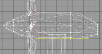
Now the texture must be placed correctly. This is done with the texture coordinates editor, located in the menu under Window->Texture-Coordinate-Editor.
First we adjust the texture for the rotor blade tops, therefore you have to select them via Groups->Select, before you open the editor.
By the way, working with the texture coordinates editor is sometimes challenging, on the following picture you see why:
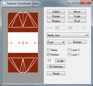
Texture coordinates editor
Firstly, the many lines and vertices are often confusing and you have to get an orientation about, and secondly, sometimes, an object
is presented from a problematic perspective, as in our case, the rotor blade in the middle.
In the drop-down list in the texture coordinates editor, where 'Front' is selected by default, the views can be selected.
The view 'Front' shows the model, how we have positioned it, "from the side". I accepted this view for editing, because the exact
distribution of pixels on the rotor blade surfaces is no matter and this view allows the fastest processing. First you should scale the view
to a reasonable size. Write a value into the textbox, before the Scale button, that fits for you and then click on the accompanying button( '4' should be okay ).
Also, you should enable the Redraw checkbox, because this will update the 3D view for each change made by you. Then you have to click on Remap and your
view should look like as on the picture above. The goal is to stretch all three rotor blade tops over the entire texture. The work is done mainly with
the four buttons Select, Move, Rotate and Scale. They have in principle the same function as in the main editor, except that the extra features
are missing.
Now to the task: first you should set the rotor blade in the middle, aside, because it is more of a hindrance than conducive.
Then drag the inner sides of the two remaining blades, to each of the opposite sides of the texture:
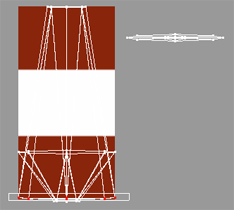
Texture mapping - ab
You should bring the two vertex-ellipses roughly on a line, to avoid distortions. Now to the trickiest part, the, from front shown, third rotor blade. If you enlarge, respectively scale it, on the Y-axis by mouse, until two vertex-ellipses can be recognized, you should be able to orient yourselves. Pick up the two ellipses and also drag them to each of the opposite sides of the texture and bring them afterwards on a line too. To avoid confusion, you can do this easily beside the texture, as long as you comply with the upper and lower limit of the texture. At the end it should look like this:
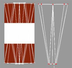
Texture mapping - c
You can leave the white texture as it is, it's not necessary to make an adjustment in the texture coordinates editor. In this case, it is okay to
work inaccurate, because when a region has the same color, so how it is partially the case with our rotor blade tops, it doesn't matter how the texture
is mapped there. But beware, whenever the texture has different values in this region, strong distortions may appear.
Now we're done with texturing. Check your result in the 3D view again and if you are contented, we go on with the next chapter.
Texturing - result
Animating the wind turbine
For the animation we must create joints first. Joints work in principle like that in the human body. Their position and orientation determine
the position of their assigned vertices. Click on Model->Joint and then add two joints by mouse click. The first should be placed in the center of
the nacelle, above the tower. It is the root joint, the top in the joint hierarchy. Then add a second joint in the center of the rotor hub, while
the root joint is selected. This one is responsible for the spinning of the rotor. To select a joint, you must, not hard to guess, click Model->Select->Joint.
Afterwards the joints has to get the vertices assigned, which should later move with the joints. The root joint gets the groups - 'tower' and 'nacelle' and the
rotor joint, the groups - 'rotor' and 'rotor blade tops' assigned. To do so, select the appropriate groups with Groups->Select and with click on Joints->Assign
they will be assigned to the selected joint in the list:
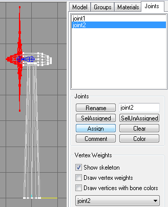
Joints tab
You can verify your assignment by clicking on Joints->SelAssigned.
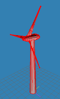
Now we can animate our wind turbine, specifically, our rotor.
For this, click on the Anim button on the bottom right in Milkshape 3D, and then click on Model->Select->Joint and select the rotor joint, so that it appears red:
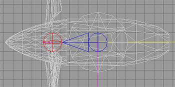
The two joints, with the selected rotor joint
Before we start, we adjust the number of frames (pictures) our animation sequence should contain. Write the desired value into the two right textboxes, next to the Anim button. I chose 39, so that every tenth frame can be set as keyframe, with a rotor, which is 90 degrees twisted further as in the last keyframe:
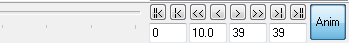
Animation bar
Now we set the first keyframe with a click in the menu on Animate->Set Keyframe. Then move the slider on the frame bar to frame 10.
Incidentally, the second textbox from the left, shows at which frame the slider is currently located.
Then twist the rotor by 90 degrees using the mouse, preferably in a view, that shows the rotor frontally (see last picture).
A click on Animate->Set Keyframe saves this pose. The same should be made at frame 20. The last frame, therefore was chosen as the 39.
frame, because we want a fairly smooth transition to the beginning of the animation, speak the first frame. We set the rotation of the rotor to -9,
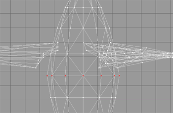
respectively 351 degrees, and click Animate->Set Keyframe, one last time. The last picture shows again, the four views,
when setting the animation sequence:
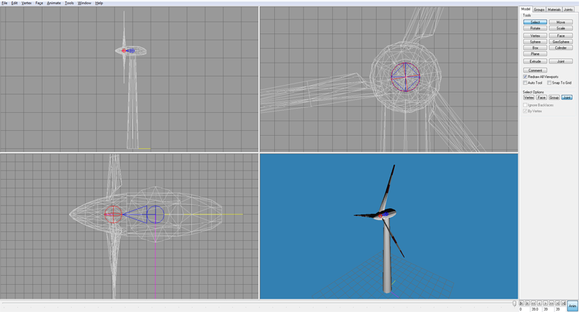
Animation
Now we can play the animation by clicking on the right-pointing arrow in the animation bar. The rotor of the wind turbine should spin. Heureka!
The task, to model, texture, and animate a wind turbine, is accomplished. Now you can save the model with the many export possibilities that Milkshape 3D offers, and import it into a 3d graphics engine.
If you should see any holes in the model, when rendering it with a graphics engine, this may be, when triangles of the model are drawn with the wrong vertex order. Selecting the affected triangles in Milkshape 3D and clicking on Face->Reverse Vertex Order in the menu, should rectify the problem, unless missing triangles are responsible.
I have already tested my model with a graphics engine and everything works well. You can download it here with textures in a zip file.
I hope, you got a good insight and you find your way in Milkshape 3D,
Christoph.
