

Tutorials
Here you will find tutorials for the topic Game Development.
| Converting Ms3d-animations to DirectX | Date: 12.5.2010 | Author: Christoph P. | Difficulty: Medium |
| Introduction to DirectX Shader | Date: 15.5.2010 | Author: Christoph P. | Difficulty: Easy |
| Dual Paraboloid Shadow Mapping | Date: 23.5.2010 | Author: Christoph P. | Difficulty: Medium |
| Introduction to Milkshape 3D | Date: 17.6.2010 | Author: Christoph P. | Difficulty: Easy |
Dual paraboloid shadow mapping
Preface
This tutorial explains the theme using a DirectX effect and shader model 3.0. Knowledge of the implementation with render targets, setting effect variables and transformations of objects are essential for the understanding of the example. The example can be transferred easily to other shader languages.
Introduction
Shadow mapping is a technique used to render shadows in computer graphics. With this method a texture with depth values (shadow map)
is created from the viewpoint of the light source. When drawing the scene the depth values of the pixels are then compared with the depth
values in the shadow map. This requires that the pixels must be transformed to the coordinate system of the light source.
Are the values lower, the pixels are in shadow.
This technique in use with only one shadow map, makes sense only with a spot light. If you want to realize a light which shines in several directions,
e.g. a point light, this method is no longer sufficient.
The most obvious solution is to use a shadow map for each direction in which the light shines.
A point light would then result in six shadow maps. By the way, this method is then called cubical shadow mapping: although it has no impact on quality,
it is very unperformant because you need to render six shadow maps.
Another technique to solve the problem is called spherical shadow mapping.
This technique uses only one shadow map like the traditional shadow mapping technique and is therefore nearly as
quickly but problematic in point of quality, because the uneven sample rate leads to distortions.
Further research brought the dual paraboloid - technology, first time described 1998 in the
publication "view-independent environment maps" from Wolfgang Heidrich and Hans-Peter Seidel.
Here should be noted that the shadow mapping problem described until now, can be found in almost identical form with environment mapping,
except that there are color values of the environment, used in the maps, instead of depth values.
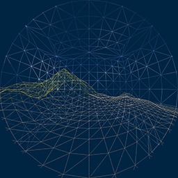
Theredo I want to show a picture presenting a paraboloid map used with dual paraboloid environment mapping.
The purpose of this picture, however, is to give you an insight into the paraboloid projection, which is difficult with a paraboloid shadow map,
as we will see later. But we want to remain on the subject dual paraboloid shadow mapping.
Paraboloid environment mapping
Paraboloid maps provide a good performance and higher quality than spherical maps. First a picture of an elliptical paraboloid, similar we will use it:
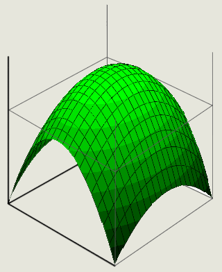
Elliptic paraboloid
A advantageous feature of paraboloids is that incident rays coming from the focal point, will be reflected parallel to the direction of the paraboloid, which facilitates the calculation of the projection:
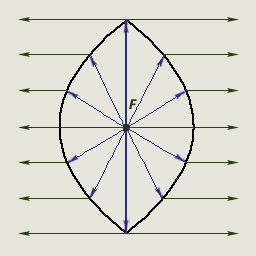
Paraboloid reflection
When using paraboloid mapping the space around the light source is divided into two hemispheres (paraboloids). There is a front and a rear hemisphere, which are put together with the open sides ahead, forming an enclosed space, as in the picture above.
Mathematic derivation
First we choose a paraboloid that is suitable for this purpose:
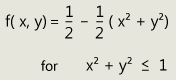
Each vertex rendered must be projected onto the paraboloid surface. A picture as explanation:
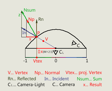
Paraboloid projection
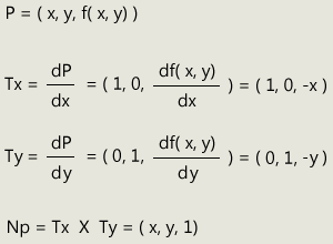
The x- and y- coordinate of the projection point must be found. These coordinates can be calculated using the normal vector at the point of projection. For this we first need the definition of the normal vector at the surface. This is determined by the cross product of the tangents. We will get the tangents from the partial derivation of the function with respect to x and y.
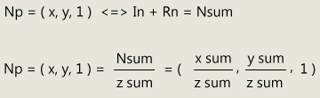
The direction vector of the incident projection ray corresponds to the normalized vertex position in the paraboloid coordinate system. If we add the reflection vector to the direction vector, we get a vector that corresponds to the normal at the point of projection, only the length is different. Because the reflection vector has the same direction as the z-axis, we only have to add 1 to the z-value of the incident vector.
If we now establish a relationship to the above derivation, it can be seen that a division of the added vector by its z-value calculates the x-and y-coordinate of the desired projection point.
Implementation
a.) Creation of the paraboloid shadow maps:
The paraboloid shadow maps must be created in the first two render passes. I used a resolution of 1024 x 1024, for the maps, but this can be chosen at will. The higher the resolution, the better the shadow quality, but the worse the performance. For the texture format it is recommended to use the R32F floating point format.
First of all, the render target for the front shadow map must be set. Next the world view matrix for the paraboloid space must be created and set as a parameter for the effect. The world matrix corresponds to a common transformation in the absolute space and the view matrix is the matrix that allows us to render the scene from the perspective of the light. The position of this matrix is the light position and the orientation can be chosen freely. I have chosen the orientation towards the objects that will be illuminated. A projection matrix is not needed, because we perform the projection manually.
Now we can implement the shader. As so often, it looks much simpler in the shader:
first the vertex shader:
First the vertices are transformed in the paraboloid space and divided by w to get homogeneous coordinates.
The meaning of g_fDir will be explained later.
Now the vertex has to be projected on the paraboloid. As we know, the normalized vertex position in the paraboloid space corresponds to the direction
vector of the incident projection ray. Therefore we normalize the vertex position now and we store the z-coordinate for the pixel shader.
Now the decisive part: we add the reflection vector (0/0/1) to the just calculated projection direction vector and we get the vector that
corresponds to the normal on the projection point. We divide it by its z-value and we get the desired x- and y- coordinate. In the example
I've done both steps in one, let this not confuse you. The calculated coordinates corresponds to the texture coordinates in the shadow map.
For the subsequent z-buffer test we have to calculate the z-value of the vertex correctly. We do this by bringing it between zero and one, using
the far and near clipping plane. We also store this value for the pixel shader. The w-value is neutralized.
Explanation of g_fDir: to avoid writing two almost identical shaders, we simply invert the z-coordinate of the vertex for the rear hemisphere. Also the back-face culling must be disabled to make this possible, because the order of the triangle vertices will be reversed when inverting the z-coordinate.
the pixel shader:
Here, only the pixels located before the clipping plane of the respective hemisphere, have to be removed and the depth of the pixels have to be written in the shadow map.
Now we render the scene once with g_fDir = 1 for the front hemisphere and once with g_fDir = -1 for the rear hemisphere and the shadow maps are created. The result should then in principle look like the following picture:

Dual paraboloid shadow map
b.) rendering of the final scene:
First the render target for the scene and some parameters for the effect must be set. Namely they are:
- the two previously created shadow maps (for PS)
- if desired, the necessary textures (for PS)
- the world and combined view projection matrix for the scene (for VS)
- the paraboloid view matrix (for PS)
- the light position in world coordinates, which is required for lighting (for PS)
- light and material colors
- the SHADOW_EPSILON, which is needed with shadow mapping to avoid unwanted artifacts
- furthermore, the required samplers
In the vertex shader is nothing that is specific to paraboloid mapping, so an explanation is not necessary here.
Now the pixel shader:
Even if the pixel shader shown below does not give the impression, again there is nothing in it that would necessarily be explained, because the calculation of the texture coordinates is the same as we used it when creating the shadow maps, except that the calculation of both hemispheres is provided here and depending in which hemisphere the vertex is located, the coordinates for one of the two paraboloids are calculated and brought between zero and one, so that the shadow maps can be read correctly. The last part in the pixel shader is the same as in the traditional shadow mapping technique: the depth values of the pixel are compared. If it is greater than the value in the shadow map, the pixel is in shadow and it only gets the texture color and ambient light. Otherwise, it is lit properly and gets all a pixel dreams of. :)
To complete the effect, the compilation of the shaders:
Now only the rendering of the scene must be done and that's it!
Conclusion to dual paraboloid shadow mapping (also valid for dual paraboloid environment mapping):
As mentioned above, paraboloid maps provide good performance and are qualitatively better as spherical maps, however, there are also drawbacks compared with cubical mapping, mainly related to the distortions from the paraboloids. One effect which may appear is, if you already transform the vertex positions to the paraboloid space in the vertex shader, when drawing the scene, a distortion would occur due to the interpolation in the rasterizer. Since we have transformed the position in the pixel shader in our example, this problem is eliminated for us. The other slightly heavier to handle problem are distortions that occur mainly at the clipping plane of the two hemispheres and become visible through cracks. But this effect is highly dependent on the resolution of the geometry. If it is high enough, the effect is smaller. You can also counteract this effect with skillful setting of this plane. You should, if possible, avoid collisions of the geometry with this plane.
As we have seen, despite small drawbacks, paraboloid maps are very useful. Because of becoming faster and faster graphics cards the resolution of the geometry is getting higher, so nothing should stand in the way for paraboloid mapping in the future.
You can download the complete example as a DirectX effect file here.
